The Landscape Lighting Voltage Drop: Preventing Dim Fixtures
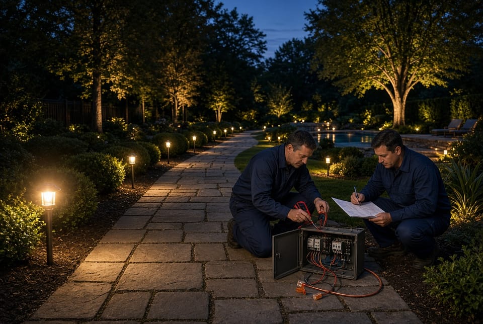
A landscape lighting system can look impressive on paper and still fail at dusk. The transformer hums. The fixtures are new. The first few path lights look crisp. Then the run continues around a bed, down a walk, or toward a distant tree—and the last fixtures look tired, amber, or barely awake. That pattern is not random. It is a design issue called voltage drop.
Fix Voltage Drop Before Dusk – Call Today
Voltage drop is the loss of electrical pressure as current travels through cable. In a 12-volt landscape system, even a modest loss matters. A fixture that needs roughly 12 volts at the lamp or driver may receive only 10.5 volts—or less—at the end of a long, crowded run. The result is dim fixtures, uneven color, and a property that never quite matches the lighting plan.
The good news is straightforward. Voltage drop is predictable. It can be calculated before a trench is opened, measured after the system is energized, and corrected with thicker wire, additional transformers, and fewer fixtures per run. Proper design prevents the problem. Guesswork invites it.
The Design Issue Behind Dim Landscape Lights
Most residential outdoor lighting is low-voltage lighting. A transformer steps household power down to a nominal 12-volt output. That lower voltage is safer to handle in soil and planting beds, but it leaves very little room for loss. On a 120-volt circuit, a one-volt loss is almost invisible. On a 12-volt circuit, a one-volt loss is a large percentage of the available power.
That is why landscape lighting is unusually sensitive to three design decisions:
- How far the cable travels from the transformer to the last fixture
- How much load that single cable is asked to carry
- How thick—or thin—the copper conductors are
When those three factors are ignored, the system still “works.” Lights turn on. The owner still sees illumination. What disappears is uniformity. The front of the run looks designed. The back of the run looks neglected. Clients often replace lamps or blame LED quality when the real fault is circuit design.
A healthy 12-volt landscape circuit should keep the farthest fixture inside a usable window, commonly near 10.8 volts or higher under full load. Many professionals target an even tighter budget—about 5% to 10% of supply voltage—so brightness stays consistent from the first fixture to the last. Crossing that line is the design failure this article exists to prevent.
How Voltage Drop Occurs
Voltage drop is not a defect in the fixture. It is physics. Copper wire has resistance. Current flowing through resistance consumes voltage. The longer the path and the heavier the current, the larger the loss.
Two conditions create most dim-fixture complaints.
Long Wire Runs
Every extra foot of cable adds resistance. The current does not travel one way. It travels out to the fixture and back to the transformer, so the electrical path is a round trip. A 120-foot one-way run is 240 feet of conductor that the current must fight through.
Long runs appear in the places homeowners want light most: driveways, deep backyards, pool perimeters, and tree lines far from the house. If the transformer stays on an exterior wall and a single cable follows the entire route, the last fixtures inherit whatever voltage is left after the cable has already paid its resistance tax.
Distance also multiplies small errors. A slightly undersized cable may look acceptable at 40 feet. The same cable at 140 feet can leave the last lights looking dull even though every fixture is identical.
Too Many Fixtures on One Run
Each fixture draws current. Current is the other half of the drop equation. A short cable with one 4-watt path light barely notices the load. The same cable feeding twelve fixtures becomes a crowded highway.
Daisy-chaining is the most common way this happens. One cable leaves the transformer, hits fixture after fixture, and keeps going. Every added lamp increases amperage on the shared conductors. Voltage sags progressively. The first light may look correct. The middle lights look softer. The last lights look like they belong to a different system.
Overloading a run is easy because LED fixtures are small. A homeowner or installer can add “just one more” uplight without feeling the weight of another halogen lamp. The wattage still adds up. So does the current. So does the drop.
Other Contributors That Make the Loss Worse
Long runs and crowded runs are the headline causes. Several field conditions make them worse:
- Wire that is too thin for the distance and load, especially 16 AWG or 18 AWG used as a main trunk
- Poor splices that add hidden resistance through corrosion, loose connectors, or nicked strands
- Transformer placement that forces every zone to travel farther than necessary
- Oversized transformer loading, where the unit is asked to carry more than about 80% of its rated capacity
- Unbalanced layouts, with most of the wattage clustered at the far end of one home run
These details do not replace the core problem. They amplify it. A clean splice will not rescue a 200-foot run of thin cable packed with fixtures. Design still comes first.
Why Low Voltage Makes Dimming So Visible
Landscape lighting looks simple because the fixtures are compact. The electrical math is not. A 10% drop on a 120-volt circuit still leaves 108 volts. A 10% drop on a 12-volt circuit leaves 10.8 volts. That is the edge of acceptable performance for many LED drivers.
Below that point, several things can happen:
- Output falls and the fixture looks dim
- Color temperature can shift warmer or uneven
- Drivers may flicker, hunt, or cycle
- The nearest fixtures still look bright, which makes the far fixtures look even worse by comparison
That contrast is why voltage drop is so often misdiagnosed. People see one bright light and one dull light and assume the dull fixture failed. In a correctly designed system, identical fixtures on the same scene should read as a family. When they do not, measure voltage at the socket or lead under load before replacing hardware.
How to Calculate Voltage Drop
Calculation turns a vague worry into a design decision. You do not need laboratory equipment to plan a run. You need four values: load, current, one-way distance, and wire resistance.
Step 1: Add the Load on That Run
List every fixture that will live on the same cable. Use the fixture’s wattage or, for many LEDs, the VA rating if the manufacturer publishes one. Add them. That total is the connected load for the run—not the whole property, just that circuit.
Example: eight 5-watt path lights and two 7-watt uplights equal 54 watts.
Step 2: Convert Load to Current
Current in amps equals load divided by voltage.
I = watts (or VA) ÷ 12
In the example: 54 ÷ 12 = 4.5 amps.
That current travels through the cable for the entire electrical loop.
Step 3: Measure One-Way Distance
Measure the actual cable route, not the straight-line map distance. Include the path around beds, under walks, and up to the transformer lugs. This is L, the one-way length in feet.
If the last fixture is 90 feet of cable away, L = 90.
Step 4: Choose Wire Gauge and Its Resistance
Thicker wire has a lower AWG number and lower resistance. Approximate copper resistance values used in landscape planning include:
- 10 AWG: about 0.999 ohms per 1,000 feet
- 12 AWG: about 1.59 ohms per 1,000 feet
- 14 AWG: about 2.53 ohms per 1,000 feet
- 16 AWG: about 4.02 ohms per 1,000 feet
These figures explain why thin cable fails on long runs. Sixteen-gauge wire has more than twice the resistance of 12-gauge wire. The same current and distance produce a much larger drop.
Step 5: Apply the Round-Trip Formula
A practical formula for two-conductor landscape cable is:
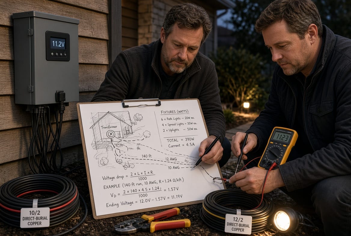
Voltage drop = (2 × L × I × R) ÷ 1,000
Where:
- L = one-way length in feet
- I = current in amps
- R = resistance in ohms per 1,000 feet
- 2 = outgoing and returning conductors
Using the example on 12 AWG at 90 feet:
Voltage drop = (2 × 90 × 4.5 × 1.59) ÷ 1,000
Voltage drop = 1.29 volts
Fixture voltage ≈ 12 − 1.29 = 10.71 volts
That result sits near the lower edge of a comfortable window. The lights may still operate, but the last fixtures are at risk of looking softer than the first. The design is not robust. A thicker conductor, a shorter run, or a lighter load would improve the margin.
Repeat the same math with 10 AWG (R ≈ 0.999):
Voltage drop = (2 × 90 × 4.5 × 0.999) ÷ 1,000
Voltage drop = 0.81 volts
Fixture voltage ≈ 11.19 volts. That is a healthier circuit.
The formula is the design conversation in compact form. Distance, current, and resistance all matter. Change one of them and the last fixture changes with it.
Practical Gauge and Distance Guidelines
Formulas keep a design honest. Field guidelines keep it efficient. They are starting points, not substitutes for the math.
- 16 AWG belongs on short jumpers or very light, nearby accent groups—not on a property-length trunk.
- 14 AWG can serve short, modest LED branches close to the transformer.
- 12 AWG is the professional default for many residential main runs, especially when the load stays near 100 watts and the one-way length stays near 100 feet.
- 10 AWG is the upgrade for longer routes, heavier zones, or runs that push past about 150 feet.
A useful memory aid is the 100/100 idea: roughly 100 feet of 12 AWG for about 100 watts. Treat it as a caution flag, not a promise. Clustered fixtures at the far end, extra splices, or a higher true VA load can exhaust that budget faster than the slogan suggests.
Also size the transformer with headroom. Add the wattage of every connected fixture, then keep the transformer at or below about 80% of its listed rating. A 60-watt connected load is not an excuse to fill a 60-watt transformer to the rim. Headroom protects voltage stability when the system is fully on.
Solutions That Prevent Dim Fixtures
Once the numbers expose a weak run, the corrections are few and reliable. The best systems often use more than one.
Use Thicker Wire
Thicker copper lowers resistance. Lower resistance lowers drop. Upgrading a main run from 16 AWG or 14 AWG to 12 AWG or 10 AWG is the most direct structural fix.
Keep thin cable where it belongs: short fixture leads. The buried trunk that feeds a bed or walk should be the heavier conductor. Replacing a long, undersized home run is more work than choosing the right gauge on day one, which is why voltage-drop planning belongs in the design phase, not the complaint phase.
Add Transformers
A second transformer is not an admission of failure. It is a layout tool. One transformer on the garage wall cannot economically feed a front walk, a rear terrace, and a far tree with equal voltage if every cable starts from the same point.
Adding a transformer closer to a distant zone shortens L. Shorter L means less drop, even if the wire gauge stays the same. Large properties often need multiple power centers, each serving a compact group of fixtures. The result is even brightness without forcing one cabinet to push current across the entire lot.
Reduce Fixtures per Run
If a single cable is carrying too much current, split the load. Create two home runs. Use a hub or “T” layout so several shorter branches leave a central point. Avoid one long daisy chain whenever the fixture count or wattage starts to climb.
Reducing fixtures per run does not mean removing light from the property. It means giving those fixtures their own electrical path. The same twelve lights that look uneven on one overloaded cable can look even when they become two six-fixture runs.
Use Transformer Taps with Care
Many landscape transformers include 12V, 13V, 14V, and sometimes 15V taps. A higher tap can offset calculated drop on a long branch. It is a useful field adjustment when the math and a meter agree that the far end is low.
Taps are not a license to ignore wire size. Raising the tap raises voltage along the entire run. Fixtures nearest the transformer can be overdriven if the tap is used as a blunt substitute for proper cable. Measure the first fixture and the last fixture. The goal is a balanced window, not a bright near light and a rescued far light at the expense of lamp or driver life.
Improve Connections and Layout Details
After the major design moves, clean up the small resistances:
- Use wet-location connectors rated for direct burial
- Keep splices tight, sealed, and free of corroded strands
- Place the transformer as close as practical to the heaviest lighting zones
- Separate high-wattage features—such as a cluster of tree uplights—onto their own run
These details protect the voltage you already calculated. They rarely replace thicker wire or a shorter run when the circuit is fundamentally oversized.
Design the System Before the Trench
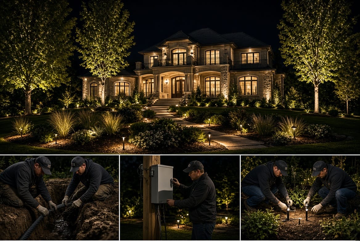
The least expensive voltage-drop correction is the one that happens on the drawing. Walk the property at the proposed fixture locations. Mark the transformer. Sketch every home run. Write the wattage on each symbol. Measure the route the cable will actually travel.
Then ask three questions of every run:
- Is the one-way distance short enough for the chosen gauge?
- Is the connected load light enough that current stays reasonable?
- If the answer to either question is no, should the design add wire thickness, add a transformer, or split the fixtures?
If a future owner is likely to add lights later, leave capacity on purpose. A circuit designed to the exact limit has no room for one more tree light. That “one more” fixture is how many systems quietly slide into dim territory two seasons after installation.
Field verification still matters. After energizing a new or repaired zone, measure voltage at the first and last fixtures under full load. A paper calculation is a plan. A meter reading is the result. If the last fixture is below the target window, adjust the design rather than hoping the eye will stop noticing.
Common Mistakes That Create Dim Lights
Most voltage-drop failures follow a short list of habits:
- Using kit-gauge cable as a long buried trunk
- Daisy-chaining an entire yard on one outgoing pair
- Mounting a single transformer far from the lights it must serve
- Adding fixtures over time without recalculating the run
- Raising a tap to hide a cable that was never sized correctly
- Assuming LED efficiency made wire gauge optional
None of those habits is mysterious. Each one increases resistance, current, or distance. The fixtures then tell the truth at night.
Prevent Dim Lights with Proper Design
Voltage drop is not an unlucky surprise. It is the predictable cost of sending current through wire. Long wire runs and too many fixtures on one circuit are the usual causes. Wire gauge and distance determine the size of the loss. Thicker wire, added transformers, and reduced fixtures per run restore even output.
A landscape lighting system should look composed from the front walk to the last tree. When distant fixtures fade, the property does not need another guess. It needs a circuit designed to deliver voltage where the light actually lives.
Warning: Do not ignore uneven brightness. Dim end-of-run fixtures are a sign the design is starving the circuit. Continuing to add lights, raise taps blindly, or replace lamps without measuring voltage can leave the same weak pattern in place—and can stress drivers on both ends of the run.
Prevent dim lights with proper design. For professional landscape lighting design, calculation, and installation help.
Call Now for Landscape Lighting Voltage-Drop Repair