The Solar Panel Voltage Drop: Understanding Wire Sizing and Distance Impact
In today’s solar energy landscape, every percentage point of efficiency matters. Voltage drop remains one of the most overlooked yet critical factors that can silently rob your solar panel system of its full potential. When electricity travels through wires from the solar array to the inverter, resistance naturally causes a reduction in voltage. The longer the wire run and the thinner the wire, the greater this voltage drop becomes—directly translating into lost power, reduced energy production, and lower overall system performance.
Maximize Solar Efficiency – Get Expert Design
Professional solar designers understand that proper electrical design is not optional; it is essential. By focusing on wire sizing and accounting for distance impact, installers can keep voltage losses to an absolute minimum. This comprehensive guide explains exactly how voltage drop occurs, why it matters for your solar investment, and how strategic wire gauge selection delivers reliable, high-efficiency results you can count on for decades.
What Is Voltage Drop in Solar Panel Systems?
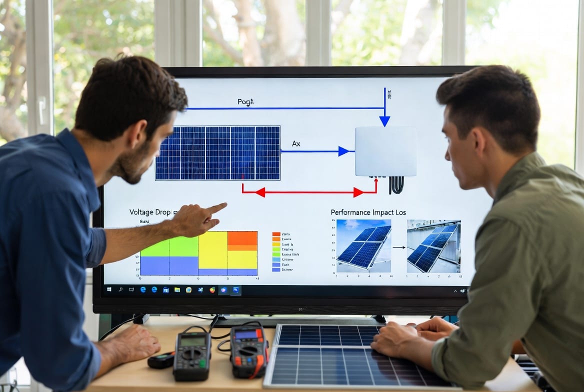
Voltage drop is the gradual decrease in voltage that occurs as direct current (DC) flows through conductor wires. In a solar photovoltaic (PV) system, panels generate DC power that must travel to the inverter before conversion to alternating current (AC) for home or grid use. Any resistance along this path reduces the voltage reaching the inverter.
Even small voltage drops compound over time. A system rated at 600 volts might deliver only 570 volts after traveling 150 feet through undersized wire. That 5% loss means your panels produce less usable electricity than their nameplate rating suggests. Industry standards recommend keeping total voltage drop under 2% for optimal performance, yet many installations exceed this threshold without proper planning.
The physics is straightforward yet powerful. Wire resistance depends on material, cross-sectional area, and length. Copper offers excellent conductivity, but it still presents resistance that grows with distance. When wire sizing is ignored, the system works harder, heats up more, and ultimately delivers less clean energy to your home or business.
How Long Wire Runs Cause Voltage Drop
Distance is the primary driver of voltage drop in solar installations. The farther the power must travel, the more opportunity resistance has to reduce voltage. Roof-mounted arrays often sit 50 to 300 feet from the inverter, while ground-mounted commercial systems can exceed 500 feet. Each additional foot increases resistance proportionally.
Consider a typical residential setup. Panels on the south-facing roof might connect to an inverter in the garage or basement. That 120-foot one-way run becomes a 240-foot round trip when calculating resistance. At higher currents—common in modern high-output modules—the effect multiplies. A 10-amp current through 10 AWG wire might experience negligible loss over 50 feet, yet the same current over 250 feet could exceed 3% voltage drop, pushing efficiency below acceptable levels.
Long wire runs also introduce other challenges. Temperature fluctuations cause wire expansion and contraction, while exposure to UV and weather accelerates insulation degradation. These real-world conditions make accurate wire sizing even more important. Professional designers always measure the actual routing path—including vertical rises and conduit bends—rather than relying on straight-line estimates.
The Impact of Voltage Drop on System Efficiency
Reduced voltage directly lowers power output because power equals voltage multiplied by current. A 3% voltage drop does not simply mean 3% less energy; the inverter may operate outside its optimal voltage window, triggering efficiency losses or even shutdowns during peak production hours.
Studies of real installations show that unchecked voltage drop can reduce annual energy yield by 4% to 8%. Over a 25-year system lifespan, that translates into thousands of dollars in lost savings. Homeowners notice higher utility bills, while commercial operators see longer payback periods. In extreme cases, excessive drop can damage sensitive inverter electronics or void manufacturer warranties.
The good news? These losses are completely preventable. With correct wire sizing and thoughtful system layout, designers routinely achieve under 1% voltage drop even on challenging long-distance runs. This level of performance ensures your solar panels deliver the maximum return on investment while operating safely and reliably.
Understanding Wire Sizing: The Key to Minimizing Losses
Wire gauge selection directly counters the effects of distance. Thicker wires (lower AWG numbers) have larger cross-sectional areas, reducing resistance and allowing current to flow with minimal voltage drop. For example, moving from 10 AWG to 6 AWG wire can cut resistance by more than half over the same distance.
Professional solar designers follow a systematic approach:
- Calculate maximum current based on panel specifications and system configuration
- Measure precise one-way distance including all conduit bends and vertical runs
- Determine acceptable voltage drop (typically 1-2% for DC circuits)
- Select appropriate wire gauge using NEC-approved tables or voltage drop calculators
- Factor in temperature and conduit fill for derating adjustments
Copper remains the preferred material for its superior conductivity and corrosion resistance, though aluminum offers cost savings on very long commercial runs when properly terminated. Always verify that chosen wire carries the necessary ampacity while staying within voltage drop limits.
Calculating Voltage Drop: Formulas and Practical Examples
Accurate calculation empowers informed wire sizing decisions. The basic formula for DC voltage drop in a two-conductor circuit is:
[ V_{\text{drop}} = 2 \times I \times R \times L ]
Where:
- ( I ) = current in amperes
- ( R ) = resistance of the wire in ohms per 1,000 feet
- ( L ) = one-way length of the wire run in thousands of feet
Percentage voltage drop is then:
[ % \text{ drop} = \left( \frac{V_{\text{drop}}}{V_{\text{system}}} \right) \times 100 ]
Consider a practical example. A 48-volt system draws 25 amps over a 150-foot one-way run using 8 AWG copper wire (resistance approximately 0.64 ohms per 1,000 feet). Plugging in the numbers:
[ V_{\text{drop}} = 2 \times 25 \times 0.64 \times 0.15 = 4.8 \text{ volts} ]
[ % \text{ drop} = \left( \frac{4.8}{48} \right) \times 100 = 10% ]
This exceeds safe limits and would significantly impair performance. Switching to 4 AWG wire (resistance 0.25 ohms per 1,000 feet) reduces the drop to approximately 3.75%, still high. Proper 2 AWG wire brings it comfortably under 2%.
Designers use these calculations for every project, often supplemented by software tools that account for temperature, conduit type, and future expansion. The result is a system engineered for maximum output rather than compromised by guesswork.
Best Practices for Wire Sizing in Solar Installations
Leading solar professionals follow proven strategies to eliminate voltage drop concerns:
- Oversize conservatively for future panel upgrades or increased loads
- Minimize distance by locating inverters as close as code and aesthetics allow
- Use high-quality stranded copper for flexibility and reduced resistance
- Install proper conduit to protect wires and simplify future maintenance
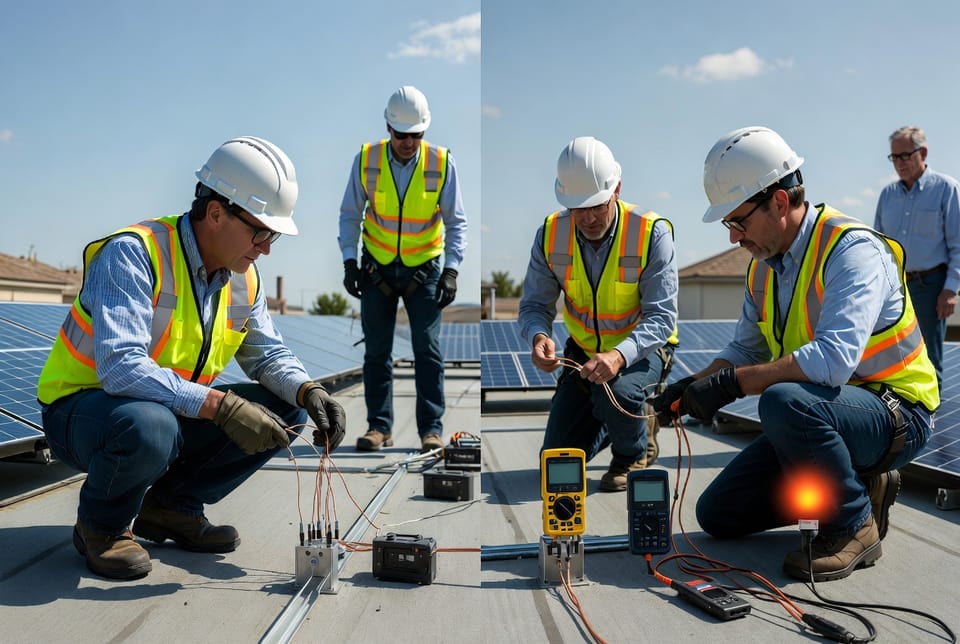
- Perform field verification with a multimeter after installation
- Document all calculations for warranty and inspection compliance
These practices not only reduce energy loss but also enhance system safety and longevity. Properly sized wires run cooler, experience less stress, and maintain consistent performance through seasonal temperature swings.
Common Mistakes and Risks to Avoid
Many installations suffer from voltage drop simply because installers prioritize cost over performance. Using the minimum gauge that passes ampacity requirements ignores the critical distance factor. Others fail to account for round-trip resistance or temperature derating, leading to hidden losses.
Risks include reduced return on investment, premature equipment wear, code violations, and even fire hazards from overheated undersized wires. DIY enthusiasts or inexperienced contractors often overlook these details, creating systems that underperform from day one.
Professional design eliminates these risks. Expert teams verify every parameter, ensuring your solar investment performs exactly as promised.
Real-World Benefits of Proper Electrical Design
Systems designed with voltage drop in mind consistently outperform expectations. Homeowners report higher energy production, faster payback periods, and greater peace of mind. Commercial installations achieve better ROI while qualifying for maximum incentives that reward high-efficiency designs.
One recent residential project spanning 220 feet from array to inverter achieved just 0.8% voltage drop through strategic 2 AWG copper wiring. Annual production exceeded projections by 7%, delivering thousands of extra kilowatt-hours over the system’s life. The clients experienced no surprises—only reliable, abundant solar power.
Conclusion: Protect Your Solar Investment Through Smart Design
Voltage drop need not compromise your solar panel system. By understanding the relationship between wire length, wire sizing, and performance, you can ensure every watt generated reaches its destination efficiently. Professional electrical design transforms potential losses into guaranteed gains.
Proper planning minimizes power loss and maximizes your return. Whether planning a new installation or optimizing an existing array, expert guidance makes all the difference.
Ready to optimize your solar system design? Our experienced team delivers efficient, code-compliant installations engineered for peak performance from day one.
Stop Power Losses – Schedule Free Consultation